Thursday, March 16, 2023

How to integrate pneumatic valves into an existing automation system ?


Pneumatic valves are essential components in automation systems, serving as control units that manage the flow of compressed air through various pneumatic devices, such as actuators, cylinders, and grippers. Integrating pneumatic valves into an existing automation system requires careful planning and execution to ensure optimal performance, reliability, and safety. In this article, we will discuss the key steps involved in integrating pneumatic valves into an existing automation system and highlight how Airmax can help you with your automation needs.

Evaluate your existing automation system. Some key factors to consider include:

Compatibility: Are the pneumatic valve you are considering compatible with your existing system? Will you need to make any modifications to the system to accommodate the new valves?

Space and layout: Do you have enough space to install the new valves? Will the valves fit within your existing layout and still allow for easy access and maintenance?

Power requirements: Do the new valves require any additional power or electrical connections? Will your existing power supply be sufficient to support the new valves?

Safety considerations: Are there any safety concerns or regulations that need to be considered when integrating new valves into your automation system?

Once you have evaluated your existing system and identified any potential issues, you can begin to plan the integration of the new pneumatic valves.

Choose the right pneumatic valves

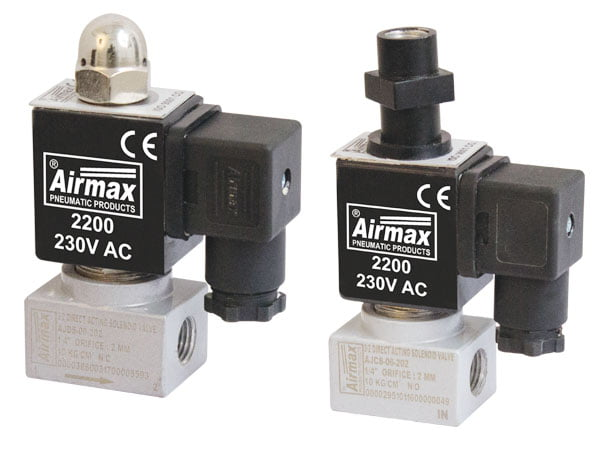
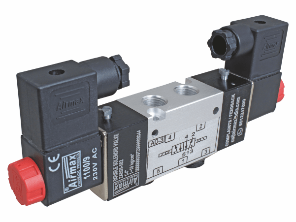
Choosing the right pneumatic valves is critical to the success of your automation system. Choosing the right type of valve for your specific application is critical to ensuring optimal performance and efficiency.

Valve size and flow rate: The size and flow rate of your valves will depend on the size of your actuators and cylinders, as well as the amount of compressed air required to operate them. Choosing the right size and flow rate is important to ensure that your system operates smoothly and efficiently

The choice of material will depend on the specific application and the operating environment.

At Airmax, we offer a wide range of pneumatic valves to meet the needs of any automation system. Our experienced engineers can help you choose the right valves for your specific application and ensure that they are installed and integrated into your system correctly.

Install and integrate the new pneumatic valves

Once you have chosen the right pneumatic valves for your automation system, it is time to install and integrate them into your existing system. 

Some key steps involved in installing and integrating new pneumatic valves include:

Prepare the system: Before installing new valves, it is important to prepare the system by shutting off power and compressed air supplies, draining any remaining air from the system, and disconnecting any electrical and pneumatic connections.

Install the valves: Once the system is prepared, install the new valves according to manufacturer instructions, taking care to properly align and secure all connections.

Test the system: After the valves are installed, test the system to ensure that it is functioning properly and safely. This may involve running test cycles and adjusting settings as needed.

At Airmax, we have extensive experience in installing and integrating pneumatic valves into existing automation systems. Our team of engineers can provide expert installation and integration services, ensuring that your new valves are installed correctly and integrated seamlessly into your existing system.

Implement control and monitoring systems

Once your new pneumatic valves are installed and integrated into your automation system, it is important to implement control and monitoring systems to ensure optimal performance and efficiency. This may involve programming and configuring your control system to properly communicate with your new valves, as well as implementing monitoring systems to track system performance and identify any issues or inefficiencies.

At Airmax, we offer a wide range of control and monitoring systems to meet the needs of any automation system. Our team of engineers can help you select and implement the right systems for your specific application, ensuring that your automation system is functioning at its best.

Regular maintenance and servicing

Regular maintenance and servicing are critical to the long-term performance and reliability of your automation system. This includes routine inspections, cleaning, and lubrication of your pneumatic valves, as well as regular testing and calibration of your control and monitoring systems.

At Airmax, we offer comprehensive maintenance and servicing solutions to keep your automation system running at its best. 

Conclusion

Integrating pneumatic valves into an existing automation system can be a complex process, but with the right planning and execution, it can lead to significant improvements in performance, efficiency, and safety. At Airmax, we offer a wide range of pneumatic valves, control and monitoring systems, installation and integration services, and maintenance and servicing solutions to meet the needs of any automation system. Contact us today to learn more about how we can help you optimize your automation system with pneumatic valves.

Friday, December 16, 2022

Everything You Need To Know About Quick Release Couplings

Whether you're a professional mechanic or a passionate DIYer, quick release couplings can make your life a whole lot easier. In this blog post, we'll take a look at everything you need to know about quick release couplings, from how they work to their advantages and disadvantages.

Introduction


A quick release coupling (QRC) is a device used to connect and disconnect two hoses, pipes, or tubes quickly and easily. They are widely used in a variety of industries, from agriculture and automotive to manufacturing and mining.


There are many different types of QRCs available on the market, each designed for a specific application. The most common type of QRC is the Camlock coupling, which is often used to connect hoses used in irrigation systems. Other popular types include the John Guest quick release coupling, the Legris quick release coupling, and the Storz quick release coupling.


When choosing a QRC for your specific application, it is important to consider the working pressure, operating temperature, and compatibility with the fluids or gases you will be using. You should also take into account the ease of use and installation, as well as the cost.


QRCs can be made from a variety of materials, including metals such as brass, stainless steel, or aluminum, or plastics such as polypropylene or nylon. The material you choose should be compatible with the fluids or gases you will be using, as well as able to withstand the operating temperature and pressure.


If you are looking for a quick and easy way to connect and disconnect hoses, pipes, or tubes, then a quick release coupling could be the ideal solution for you.


What are quick release couplings?


Quick release couplings (QRCs) are devices used to quickly and easily connect or disconnect two lines of fluid flow, most commonly in hydraulic or pneumatic systems. They are also sometimes called quick disconnect fittings, quick connect fittings or quick release valves. QRCs come in a wide variety of sizes and styles, but all operate on the same basic principle: a simple push-and-twist motion is used to engage or disengage the coupling, without the need for tools or fasteners.


There are many advantages to using QRCs instead of traditional threaded fittings. First, they save time and labor by eliminating the need to thread or unthread pipes and hoses. Second, they reduce the risk of leaks because there is no need to disassemble and reassemble components; once the coupling is engaged, it forms a secure seal. Third, QRCs are often easier to use in tight spaces because they do not require aligning two threaded parts. Finally, QRCs can be used with a wide range of materials, including metals, plastics, and rubber.


QRCs are available in a variety of sizes and configurations to suit different applications. The most common type is the push-to-connect fitting, which uses a spring-loaded sleeve to hold the fitting in place until it is pushed onto the tubing. Another popular type is the cam-and-groove coupling, which consists of two interlocking halves that are squeezed together to form a leak-proof seal. There are also specialized QRCs designed for high-pressure applications, such as those found in hydraulics systems.


When choosing a QRC for your application, it is important to consider the maximum operating pressure and temperature as well as compatibility with the materials you will be using. You should also make sure that the coupling you select meets any relevant safety standards. Quick release couplings are an essential part of many industrial operations, so it is important to choose the right one for your needs.


How do quick release couplings work?


Quick release couplings work by using a simple push-and-twist motion to engage or disengage the coupling. This motion is possible because the coupling consists of two parts: a body and a sleeve. The body has a groove that the sleeve fits into, and the sleeve has a tab that locks into the body. To connect the two parts, the sleeve is pushed onto the body until the tab snaps into place. To disconnect them, the tab is pushed in and the sleeve is twisted and pulled off.


There are many advantages to using quick release couplings instead of traditional threaded fittings. Quick release couplings are much faster and easier to use, and they require no tools or fasteners. This makes them ideal for use in tight spaces or situations where time is of the essence. Quick release couplings are also less likely to leak, making them a safer option overall.


When choosing a quick release coupling, it is important to consider the maximum operating pressure and temperature as well as compatibility with the materials you will be using. Quick release couplings are available in a variety of sizes and configurations to suit different applications, so be sure to select one that meets your specific needs.


Applications of quick release couplings


There are many applications for quick release couplings. Quick release couplings are commonly used in hydraulic and pneumatic systems, but can also be used in other fluid transfer applications. Quick release couplings are often used in situations where time is of the essence, such as in emergencies where every second counts. Quick release couplings are also used in situations where traditional threaded fittings would be difficult or impossible to use, such as in tight spaces.


Quick release couplings can be used in a wide variety of industries, including automotive, aerospace, and manufacturing. In the automotive industry, quick release couplings are commonly used in fuel lines and brake lines. In the aerospace industry, quick release couplings are often used to connect oxygen hoses and hydraulic lines. In manufacturing applications, quick release couplings can be used to connect air lines, water lines, and gas lines.


No matter what the application, quick release couplings offer several advantages over traditional threaded fittings. Quick release couplings are faster and easier to use, and they require no tools or fasteners. This makes them ideal for use in tight spaces or situations where time is of the essence. Quick release couplings are also less likely to leak, making them a safer option overall.


When choosing a quick release coupling, it is important to consider the maximum operating pressure and temperature as well as compatibility with the materials you will be using. Quick release couplings are available in a variety of sizes and configurations to suit different applications, so be sure to select one that meets your specific needs.


Advantages of quick release couplings


There are many advantages to using quick release couplings instead of traditional threaded fittings. Quick release couplings are much faster and easier to use, and they require no tools or fasteners. This makes them ideal for use in tight spaces or situations where time is of the essence. Quick release couplings are also less likely to leak, making them a safer option overall.


When choosing a quick release coupling, it is important to consider the maximum operating pressure and temperature as well as compatibility with the materials you will be using. Quick release couplings are available in a variety of sizes and configurations to suit different applications, so be sure to select one that meets your specific needs.


Disadvantages of quick release couplings


There are a few disadvantages to using quick release couplings, but they are generally outweighed by the advantages. One downside is that quick release couplings can be accidentally disconnected if the tab is not fully locked into place. Another potential disadvantage is that quick release couplings are not always compatible with all types of materials. Be sure to check compatibility before using quick release couplings with your specific materials.

Saturday, December 10, 2022

Advantages and Disadvantages of Trunnion Mounted Ball Valve

 Trunnion mounted ball valves are one of the most popular types of valves used in a variety of industries. But what are they and what are the advantages and disadvantages of using them?

Introduction


A trunnion mounted ball valve is a type of valve that is designed to be installed in between two pieces of pipe. The valve has a spherical shape and is equipped with a trunnion, which is a cylindrical rod that extends from the body of the valve. The trunnion allows the ball to rotate in a horizontal plane, which allows the flow of fluid to be controlled.


The Advantages of Trunnion Mounted Ball Valves Include:


1. The ability to control the flow of fluid through the valve by rotating the ball in a horizontal plane.

2. The ability to isolate sections of pipe without having to shut down the entire system.

3. The ability to withstand high temperatures and pressures.

4. The ability to be installed in difficult-to-reach places.

5. The ability to be used in a wide variety of applications, including oil and gas, petrochemical, chemical, power generation, and water treatment plants.


The Disadvantages of Trunnion Mounted Ball Valves Include:


1. The need for regular maintenance and inspection due to the moving parts within the valve.

2. The potential for leaks if the seals are not properly maintained.

3. The need for trained personnel to operate and maintain the valve.

What is a Trunnion Mounted Ball Valve?


A trunnion mounted ball valve is a type of valve that uses a ball as a shut-off or control element. The ball is rotatably mounted on a trunnion, which is a cylindrical post that supports the ball. The trunnion is typically located at the top and bottom of the valve body, and the ball is connected to the actuator via the trunnion.


Trunnion mounted ball valves are often used in high pressure and high temperature applications, as they provide superior performance compared to other types of valves. They are also suitable for use in corrosive environments.

Advantages of Trunnion Mounted Ball Valves Include:


- Excellent sealing performance - Trunnion mounted ball valves have an excellent sealant performance because the ball is supported by two trunnions, one at the top and one at the bottom. This ensures that there is no chance of the ball becoming dislodged and causing a leak.


- Reduced wear and tear - Trunnion mounted ball valves have reduced wear and tear because there are no moving parts in contact with each other. This reduces friction and wear, and prolongs the life of the valve.


- Easy maintenance - Trunnion mounted ball valves are easy to maintain as there are no complex moving parts. This makes it easy to identify any problems and repair them quickly.

Disadvantages of Trunnion Mounted Ball Valves Include:


- Higher cost - Trunnion mounted ball valves are typically more expensive than other types of valves due to their superior performance and durability.


- Limited sizes - Trunnion mounted ball valves are available in limited sizes due to their construction.

Advantages of Trunnion Mounted Ball Valve


Advantages of trunnion mounted ball valves include excellent sealing performance, reduced wear and tear, and easy maintenance.


Trunnion mounted ball valves offer an excellent seal due to the design of the valve. The ball is rotatably mounted on a trunnion, which is a cylindrical post that supports the ball. This design prevents the ball from being forced out of the valve during operation, ensuring that the seal is maintained.


The reduced wear and tear of trunnion mounted ball valves is another advantage of this type of valve. The ball is supported by the trunnion, which prevents it from rubbing against the sides of the valve body. This reduces friction and wears, extending the life of the valve.


Trunnion mounted ball valves are also easy to maintain. The design of the valve makes it easy to access all parts of the valve for inspection or repair. This makes it possible to keep the valve in good working condition with minimal downtime.

Disadvantages of Trunnion Mounted Ball Valve


The main disadvantage of trunnion mounted ball valves is their cost. They are typically more expensive than other types of valves, such as butterfly valves. This is due to the increased complexity of the design and the materials used. Trunnion mounted ball valves are also available in limited sizes. This can be an issue in applications where a larger valve is required.

Conclusion


In conclusion, trunnion mounted ball valves offer many advantages over other types of valves, including excellent sealing performance, reduced wear and tear, and easy maintenance. However, they are also more expensive and available in limited sizes. When deciding whether or not to use a trunnion mounted ball valve in an application, it is important to consider the specific needs of the project.

Wednesday, December 7, 2022

Three And Two Way Direct Acting Solenoid Valve: Everything You Need To Know

 Solenoid valves are an essential part of many different types of machinery and equipment. They are used to control the flow of fluids, gases, or even dry materials. A direct acting solenoid valve is a type of valve that uses a solenoid to control the flow of fluid.


There are many different types of direct acting solenoid valves, each with its advantages and disadvantages. Selecting the right valve for your application is essential to ensure that your machinery or equipment operates correctly.


In this blog post, we will take a closer look at three and two way direct acting solenoid valves. We will discuss what they are, their advantages and disadvantages, and how to select the right valve for your application.

Introduction


A solenoid valve is a device used to control the flow of liquids and gases. They are often used in plumbing and industrial applications. Solenoid valves can be classified into two main types: direct acting and indirect acting.


Direct acting solenoid valves have a plunger that is directly connected to the solenoid coil. When the coil is energized, the plunger is pulled up and allows fluid to flow through the valve. Indirect acting solenoid valves have a diaphragm that is actuated by a lever that is connected to the solenoid coil. When the coil is energized, the lever pulls on the diaphragm and opens the valve.


There are two main types of direct acting solenoid valves: three-way and two-way. Three-way solenoid valves have three ports: one for the inlet, one for an outlet, and one for the exhaust. Two-way solenoid valves have two ports: one for an inlet and one for an outlet.


3 2 way direct acting solenoid valve is used to control the flow of fluids in two directions. They are often used in applications where there is a need to switch the direction of flow, such as in irrigation systems. Two-way solenoid valves are used to control the flow of fluids in one direction only. They are often used in applications where there is a need to shut off or regulate the flow of fluids, such as in plumbing systems.


Solenoid valves can be made from a variety of materials, including brass, stainless steel, plastic, and composite. They can be either Normally Closed (NC) or Normally Open (NO). NC solenoid valves close when energized and open when de-energized. NO solenoid valves open when energized and close when de-energized.


Solenoid valves are available in a wide range of sizes and ratings. The size of a solenoid valve is determined by its port size, which is typically expressed in inches or millimeters. The rating of a solenoid valve indicates its maximum operating pressure and temperature.

What is a Direct Acting Solenoid Valve?


A direct acting solenoid valve is a device that uses an electromagnet to control the flow of fluid or gas in a piping system. The electromagnet is activated by an electric current, which creates a magnetic field that opens or closes the valve. Direct acting solenoid valves are used in a variety of applications, including controlling the flow of water in plumbing systems and regulating the pressure of air in pneumatic systems.

Types of Direct Acting Solenoid Valves


There are three main types of direct acting solenoid valves: two-way, three-way, and four-way valves. Two-way valves are the most common type of valve and are used to control the flow of fluid or gas in a piping system. Three-way valves are used to control the flow of fluid or gas in a piping system with three ports, while four-way valves are used to control the flow of fluid or gas in a piping system with four ports.

Advantages of Direct Acting Solenoid Valves


There are many advantages of using a direct acting solenoid valve over other types of valves. One advantage is that they are less likely to stick in the open or closed position due to the magnetic field created by the electric current. Another advantage is that they can be opened or closed very quickly, which is important in applications where a fast response time is needed. Additionally, direct acting solenoid valves are less likely to leak than other types of valves, making them ideal for use in applications where leakage must be avoided.

Disadvantages of Direct Acting Solenoid Valves


While direct acting solenoid valves offer several advantages, there are also some disadvantages to using them. One of the main disadvantages is that they can be expensive to purchase and maintain. Additionally, direct acting solenoid valves may not be suitable for all applications. For example, they are not typically used in applications where the flow of fluid or gas needs to be controlled very precisely.

How to select the right Direct Acting Solenoid Valve for your application


When selecting a direct acting solenoid valve, several factors must be considered in order to ensure that the correct valve is selected for the application. The first factor to consider is the type of fluid or gas that will be flowing through the valve. The second factor to consider is the maximum flow rate of the fluid or gas. The third factor to consider is the pressure of the fluid or gas. The fourth factor to consider is the temperature of the fluid or gas.


The type of fluid or gas that will be flowing through the valve is an important consideration because different fluids and gases have different properties. For example, some fluids are corrosive while others are not. Some gases are flammable while others are not. It is important to select a valve that is compatible with the type of fluid or gas that will be flowing through it.


The maximum flow rate of the fluid or gas is another important consideration when selecting a direct acting solenoid valve. The flow rate refers to the amount of fluid or gas that can flow through the valve in a given period. It is important to select a valve with a flow rate that is sufficient for the application. If the flow rate is too low, the system may not function properly. If the flow rate is too high, there may be excessive pressure on the piping system, which could lead to leaks or other problems.


The pressure of the fluid or gas is also an important consideration when selecting a direct acting solenoid valve. The pressure refers to the force with which the fluid or gas flows through the valve. It is important to select a valve with a pressure rating that is higher than the maximum pressure that will be present in the system. If the pressure rating of the valve is too low, there may be leaks or other problems in the system.


The temperature of the fluid or gas is also an important consideration when selecting a direct acting solenoid valve. The temperature refers to the average temperature of the fluid or gas as it flows through the valve. It is important to select a valve with a temperature rating that is higher than the maximum temperature that will be present in the system. If the temperature rating of valves is too low, there may be temperature-related problems in the system, such as freezing or boiling.


Monday, November 28, 2022

How The Directional Control Valve Works: A Comprehensive Guide

 A directional control valve is a vital piece of equipment in many industrial and commercial applications. But what exactly is a directional control valve, and how does it work?

In this comprehensive guide, we'll answer those questions and more. We'll explain the working principle of a directional control valve, explore the different types of valves available, and offer advice on how to select the right valve for your needs.


So whether you're a complete beginner or simply need a refresher, read on to learn everything you need to know about directional control valves.


Introduction


A directional control valve is a fluid flow control device that allows fluid to flow in only one direction. The valve consists of a body with two or more ports, a spool, and a spring. The body has an inlet port and one or more outlet ports. The spool is fitted inside the body and has a hole drilled through it. The spring sits on top of the spool and pushes down on it.


When the valve is in the open position, the inlet port is connected to the outlet port and fluid can flow through the valve. When the valve is in the closed position, the inlet port is blocked off from the outlet port and fluid cannot flow through the valve.


The directional control valve is used to control the direction of fluid flow in a hydraulic or pneumatic system. The valve allows fluid to flow in only one direction, which prevents damage to system components caused by reverse flow. The valve also allows for directional changes in fluid flow, which are necessary for many industrial and agricultural applications.

What is a directional control valve?


A directional control valve is a type of valve used to control the direction in which fluid flows. The valve is typically located between two pieces of equipment, such as a pump and a motor, and is used to direct the flow of fluid from one to the other.


Directional control valves are often used in hydraulic systems, where they are used to control the flow of hydraulic fluid. They can also be used in pneumatic systems, where they are used to control the flow of air. In both cases, the valves are used to control the direction of flow, as well as the rate of flow.


Directional control valves are available in a variety of sizes and configurations. The most common type of valve is the check valve, which allows fluid to flow in only one direction. Other types of directional control valves include relief valves, which relieve pressure from a system; and solenoid valves, which are controlled by an electric current.

The Working Principle of a Directional Control Valve 


A directional control valve is a valve used to control the direction in which fluid flows. The valve is located between two pieces of equipment and is used to direct the flow of fluid from one to the other. Directional control valves are often used in hydraulic and pneumatic systems to control the direction of flow, as well as the rate of flow. Check valves, relief valves, and solenoid valves are all types of directional control valves.


The working principle of a directional control valve is relatively simple. When the valve is in the open position, fluid can flow freely through it from one port to another. When the valve is in the closed position, fluid cannot flow through it. The position of the valve is controlled by a handle or lever that is connected to the Valve stem.

The Different Types of Directional Control Valves 


There are many different types of directional control valves, each with its own unique purpose and function. The most common type of valve is the check valve, which is used to prevent fluid from flowing in the wrong direction. Relief valves are used to relieve pressure in a system, and solenoid valves are used to control the flow of fluid using an electric current.


Check valves are the most common type of directional control valve. They are typically used to prevent fluid from flowing in the wrong direction. Check valves are often used in hydraulic and pneumatic systems to ensure that fluid flows in only one direction. The check valve is opened by the flow of fluid in the correct direction and is closed by the flow of fluid in the wrong direction.


Relief valves are another type of directional control valve. They are used to relieve pressure in a system by allowing fluid to flow in only one direction. Relief valves are often used in hydraulic and pneumatic systems to protect equipment from damage caused by excessive pressure. The relief valve is opened by the flow of fluid in the correct direction and is closed by the flow of fluid in the wrong direction.


Solenoid valves are another type of directional control valve. They are used to control the flow of fluid using an electric current. Solenoid valves are often used in hydraulic and pneumatic systems to control the direction of flow, as well as the rate of flow. The solenoid valve is opened by the flow of electric current through it and is closed by the lack of electric current.

How to Select the Right Directional Control Valve for Your Needs 


There are many different types of directional control valves on the market, each with its own unique purpose and function. So, how do you know which valve is right for your needs? When choosing a product, consider the following factors:


The first factor to consider is the type of fluid you will be using. Different fluids have different properties, and some fluids are not compatible with certain types of valves. For example, if you will be using a highly viscous fluid, you will need a valve that can handle that type of fluid.


The second factor to consider is the pressure of the fluid. Different valves have different pressure ratings, and you need to make sure that the valve you select can handle the pressure of your system. If you select a valve that is not rated for the pressure of your system, it could fail and cause serious damage.


The third factor to consider is the flow rate. Different valves have different flow rates, and you need to select a valve that can handle the flow rate of your system. If you select a valve that has a lower flow rate than your system requires, it could restrict the flow of fluid and cause problems.


The fourth factor to consider is the environment in which the valve will be used. Some valves are not designed for use in certain environments, such as extreme cold or extreme heat. Make sure that the valve you select is designed for use in the environment in which it will be used.


The fifth factor to consider is the size of the valve. Some valves are very large, and some are very small. You need to make sure that the valve you select is the correct size for your needs. If you select a valve that is too small, it could restrict the flow of fluid and cause problems. If you select a valve that is too large, it could be difficult to install or operate.


Once you have considered all of these factors, you should be able to narrow down your choices and select the right directional control valve for your needs.

Conclusion


In conclusion, the directional control valve is a vital component in many different types of machinery and systems. It is important to select the right valve for the specific application, as there are many different types of valves on the market. Consider the type of fluid, the pressure of the fluid, the flow rate, the environment in which the valve will be used, and the size of the valve when making your selection.


Tuesday, September 13, 2022

What are the FRL unit and what state are their functions?

 Express the capability of every part of FRL. Reply: FRL Unit: It is an administration unit utilizing the Pneumatic framework which blends three gadgets named Channel, Controller, and Lubricator. The capability of FRL unit Channel (F) - 1) To eliminate the micron and sub-micron particles present in the entering air of the blower.


What are the uses of the FRL units?


Pneumatic Lubricators Like tension controllers, the lubricator capability of an FRL unit guarantees that the air is dosed with a limited quantity of oil to assist pneumatic parts in working successfully. Lubricators guarantee that the right measure of oil is being utilized to decrease the grating between moving parts.


Airmax Pneumatic ltd is the leading frl unit for compressed air. We offer various types of industrial valves like ball valves, butterfly valves, control valves, plug valves, and many more. 


What do you mean by FRL?


The shortening FRL is utilized with the signifying "For Genuine" as an explanation, to underline that the speaker is being honest. It is likewise utilized as an inquiry (i.e., "For Genuine?") to communicate shock or doubt.


Which oil is utilized in the FRL unit?


SAE oil-based cleanser auto engine oil. On the off chance that you can't view it as 10wt. or on the other hand 20wt. the oil then 10w30 SAE oil-based cleanser auto engine oil might be utilized. Avoid manufactured oils for they separate and form a dark oil substance in the unit.


How would I choose an FRL unit?


FRL units guarantee the air quality for your instruments, streamlining devices' performance and life expectancy.


  • Think about your current circumstance:

  • Select the right sort of FRL.

  • Incorporate your airline establishment string and norms in with the general mish-mash:

  • Consider the air stream required by the device:


What is FRL unit Mcq?


Clarification: The FRL unit doesn't comprise the air channel. It contains an Air dryer, Air controller, and Air lubricator. The air channel eliminates the residue particles from compressed air and permits clean dry compressed air to the framework. The stream control valve controls the pace of the stream of compressed air.


Which among coming up next isn't a part of the FRL unit?


Which among coming up next isn't part of the FRL unit? Clarification: The FRL unit doesn't comprise the air channel. It contains an Air dryer, Air controller, and Air lubricator. The air channel eliminates the residue particles from compressed air and permits clean dry compressed air to the framework.


What are FRL units and what do they do?


What do FRL units do? An FRL unit is included a channel (F), controller (R), and lubricator (L). They are much of the time utilized as one unit to guarantee clean air in a pneumatic framework yet can likewise be utilized separately.


Would it be advisable for me to introduce an FR or FRL unit?


It is prescribed to introduce an FR unit assuming that your gear is self-greasing up and an FRL unit on the off chance that your hardware requires oil. It is critical to comprehend the air necessities of your framework and parts to be aware of and which parts of an FRL unit are required.


For what reason do I want an FRL in a pneumatic framework?


Having a legitimate FRL unit introduced in a pneumatic framework gives the higher unwavering quality of the parts downstream, diminished power squanders because of over-compression, and expanded part lifetime. The three parts cooperate to do the accompanying:

Sunday, September 11, 2022

What are single-acting pneumatic cylinders?

 Pneumatic cylinders, air cylinders, pneumatic actuators, or pneumatic drives, are moderately straightforward mechanical gadgets that utilize the energy of compacted air and transform it into direct movement. Lightweight and low upkeep, pneumatic cylinders for the most part work at lower speeds and less power than their wastewater-driven electric partners, yet are a clean and practical choice for dependable straight movement in numerous modern conditions. The most widely recognized plan comprises a cylinder or cylinder that is fixed on the two finishes, with a cap toward one side and a head at the opposite end. The cylinder contains a cylinder, which is connected to a bar. The bar moves all through one finish of the cylinder, incited by compacted air. Two fundamental styles exist single-acting and twofold acting.


In a single-acting pneumatic cylinder, the air is provided through one port side of the cylinder, making the cylinder bar stretch out in one bearing for an errand, for example, lifting an item. The opposite side vents air to the climate. Development the other way happens most frequently through a mechanical spring, which returns the cylinder bar to its unique or base position. A few single-acting cylinders use gravity, a weight, mechanical movement, or a remotely mounted spring to control the return stroke, albeit these plans are more uncommon. Conversely, twofold acting pneumatic cylinders highlight two ports that supply packed air to both broaden and withdraw the cylinder bar. Twofold acting plans are undeniably more commonplace all through the industry, with an expected 95% of utilizations utilizing this cylinder style. Nonetheless, in specific applications, a single-acting cylinder is the most financially savvy and proper arrangement.


In a single-acting cylinder, the plan can be "base position short" with spring return, or "base situation in addition to" with spring broaden. This relies upon whether the compacted air is utilized to control the out-stroke or the in-stroke. One more method for contemplating these two choices is to go back and forth. In the push configuration, pneumatic force makes a push, which pushes the cylinder. With the draw configuration, pneumatic force delivers a push that pulls the cylinder. The most broadly indicated type is pressure-broadened, which utilizes an interior spring to return the cylinder to its base position when the air depletes. One benefit of the single-acting plan is that in the event of one or the other power or strain misfortune, the cylinder consequently gets back to its base position. A detriment of this style is the somewhat conflicting result force during a full stroke because of the restricting spring force. Stroke length is additionally restricted by the space the compacted spring expects, as well as accessible spring lengths.


For position location, a magnet can be introduced on the cylinder. Sensors mounted on the cylinder body can then accumulate data from the attraction and decide the cylinder position. Corridor impact sensors and reed switches are frequently utilized for this reason. One more cylinder part to consider includes padding. As packed air enters the cylinder, the cylinder will move rather rapidly and possibly cause a hard effect against the head or end cap. To abstain from focusing on cylinder parts and sending vibration to the remainder of the machine, padding can be utilized at the finishes of the cylinder. For more modest cylinders, which many single-acting cylinders will generally be, adaptable safeguards made of polyurethane elastomers are frequently utilized. These guards are introduced on the head and end covers or coordinated into the actual cylinder.


Additionally remember that with single-acting cylinders, work is lost because of the restricting spring force. This power decrease should be considered while measuring this cylinder type. Width and stroke are the main variables to consider during estimating computations. Breadth alludes to cylinder distance across, which characterizes its power compared with the gaseous tension. Accessible cylinder distances across are characterized by the cylinder type and ISO or different principles. Stroke characterizes the number of millimeters the cylinder and cylinder pole can travel. A basic guideline is that the bigger the cylinder bore is, the more prominent the power yield. Common cylinder bore sizes range from 8 to 320 mm.


The last thought is a mounting style. Contingent upon the producer, numerous setups are accessible. Probably the most widely recognized incorporate foot mount, tail mount, back turn mount, and trunnion mount. The most ideal choice is not entirely settled by the particular application and other framework parts.

Directional Control Valve Solutions

In industries where precision, reliability, and efficiency are paramount, the choice of directional control valves plays a pivotal role. The...